Induction Case

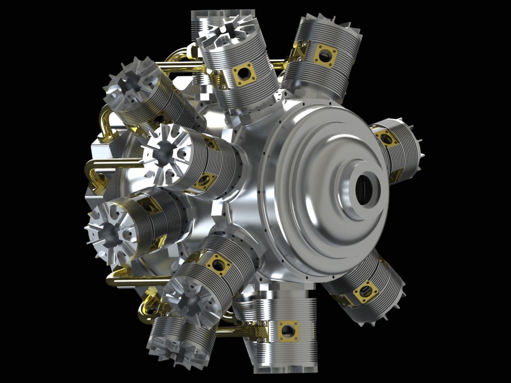
The induction case is cut from a 9in round. It attaches to the rear case and houses the impeller which supplies air/gas mixture to the cylinders under pressure. 


At 9 inches it was too large to hold in the four jaw. I hogged out the rear of the induction case using D2nc’s spiral clearing wizard. This allows the removal of material between an inside and outside diameter. 

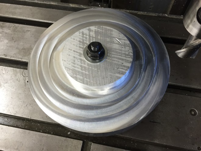
Gripping the hub formed in the rough out, I turned the inside of the case to finished dimensions except for the fillet radius outside of the lip. The meat here will be used for chucking to enable machining the rear of the case and cleaned up later. 


The rear of the induction case has been completed. The mating surface for the bell housing has been formed and the protuding material tapered to allow it to fit inside the bell. 


Rear Case

The rear case is a fairly straight forward turning job. It has to be cut to finished dimensions before the cylinder flats and case profiling can be done. 


The internal cavity has a 4.5 deg back wall, inside and out to support the main bearing. As in the front case the bearing hole is cut .001 undersize for a press fit. 


The outside of the rear case has two reference lips cut at 7 in and at 6.680 which will be used during the profiling. There is also a ring at 6 in. to mate with the induction case. 

Middle Case

The middle case is at the heart of the engine. It sits between the front and rear cases. It has two cavities on either side that create the internal space in which the crank cheeks rotate.

The picture above shows the completed middle case front cavity. The center hole which holds a bronze bearing for the crankshaft is bored through, and the lip at the edge of the case is cut in the same setup to make it concentric with the bearing hole.

Back to the mill to hog out the rear cavity before finishing it on the lathe. I use a coaxial indicator to pick up the center of the bored hole.

Living up to the web sites name, hogging out with a 1 inch end mill creates lots of swarf. Both the main pocket and step being cut are created using D2nc. You can see in the image the tool is ramped into the material using D2nc’s ramping feature.

The middle case is returned to the lathe and the rear cavity is completed to finished dimensions. The recess in the center of the case will house the two oil pumps, pressure and scavenge, which are contained in the engine. Once again the lip which mates to the rear case is machined concentric to the bearing hole.


Front case

There are 7 cases that make up the crankcase. They are the bearing case, gear case, front case, middle case, rear case, induction case and bell housing. The front, middle and rear form the core to which the two rows of cylinders are mounted. These three need to machined and strapped together for machining the flats and profiling between the flats.

The interior of the front case turned to finished dimensions. The case is 7 1/2 in round and the internal cavity is 6 in. In the picture you see it mounted in the 4 jaw chuck on my Southbend 10k lathe which has a 10 in swing.  The lip you see in the image is concentric to the bearing cavity in the center and mates to the middle case to keep all three in line. The bearing cavity has a press fit to one of the two SFK-6005 main bearings in the engine. The other main bearing is held in the rear case.

Flipping the case over caused the lip to land on the non ground part of the chuck jaw so I could not rely on that to square the front of the case to the rear. My solution was to use 8 magnets, 2 per jaw, to create a standoff so the lip was not in contact with the jaw as seen in the image below.

The front case is turned to finished dimensions ready to be mated to the middle case behind and the gear case in front.

The step near the outer edge is the mate ring for the gear case and the step on the outer edge is a 7 in diameter reference surface which will be used later during profiling. The profiling will be just below this so it will be machined away.

Crankshaft gear & square drive

I wanted to use D2nc to cut the gear on the crankshaft. The problem was that D2nc had no way of generating gear cutting gcode, so that was the first task. To add gear cutting gcode ability to D2nc, which I did in the recently released version 2.10.7. I tested it by generating the code to make this cut. Worked perfectly.

To extend the life of the gear cutter, I used the constant volume modified algorithm in D2nc which reduces the cut load on the first pass and uses constant volume material removal for subsequent passes. The other options are constant volume and fixed depth per pass.

Below you see the completed gear cut. I decided to take advantage of the setup used to cut the gear and also cut the square drive which connects to a broached 1/2in square hole in the crank cheek. Here again I used D2nc’s “CL + 4th Idx” path feature to index a simple linear cut 4 times at 90 deg intervals.

Crankshaft

So you have to start somewhere and why not choose the center of the engine? I’m starting with the crankshaft. The crankshaft is assembled from nine separate pieces and this is the first of them, the front that will hold the prop, and drive the sleeve gear train.

The crankshaft is made of 303 stainless. Here the gear blank is turned to size, bearing shoulder created in one setup to ensure they are concentric.

Sleeve Valve Radial Build

I’m starting to build a 1/4 scale Bristol Hercules 14 cylinder sleeve valve radial engine. There were 57,400 of these engines built, mainly during WWII where they powered several of the Royal Air Force bombers and fighter bombers.

The scale model plans were created by Lee Hodgson of Ageless Engines and although not released yet, he will make them available for purchase once all the kinks have been ironed out. In creating the plans, Lee took measurements and worked of a full size engine.

As part of an effort to validate the plans for Lee, my first step was to create a 3D computer model of the major parts to check for errors, fits, interference etc…  Below are some of the rendering from the modeling process.

asm5

The completed engine will be about 18 inches in diameter and weigh in at around 50 lbs.

asm7

This front view of the engine shows how clean and streamline it is.

asm3

The estimated build time for this engine is around 2000 hours. I plan to post my progress on this blog. Feel free to follow along, it should be a fun ride.